English
 中文
中文 Español
 française
 العربية
 Русский
 Toys Testing Equipment
 Physical & Mechanical Testing
- Flammability Testing
- Clamps for Toys Testing
- Electronic Toy Testing Equipment
- ISO8124-4,EN71-8
- Footwear Testing Equipment
- Fatigue Testing Equipment
- Flexing Test Equipment
- Impact Testing Equipment
- Abrasion Testing Equipment
- Waterproofness Tester
- Friction & Slip Testing
- Tensile Testing Machine
- Environmental Test Chamber
- Building Material Flammability Test Equipment
- Paper Testing Equipment
- Spectacle Frames Testing Equipment
- Oil Analysis Testing Equipment
- Lab Test Equipment
- Electronic Testing Equipment
- Stationery Testing Equipment
- Flammability Test Equipment
- Furniture Testing Machine
- Mattress Testing Machine
- Table Testing Machine
- Chair Testing Machine
- Textile Testing Equipment
- Fabric and Garment Testing Instruments
- Color Fastness Testing Equipment
- Toys Testing Equipment
- Footwear Testing Equipment
- Tensile Testing Machine
- Environmental Test Chamber
- Building Material Flammability Test Equipment
- Paper Testing Equipment
- Spectacle Frames Testing Equipment
- Oil Analysis Testing Equipment
- Lab Test Equipment
- Electronic Testing Equipment
- Stationery Testing Equipment
- Flammability Test Equipment
- Furniture Testing Machine
- Textile Testing Equipment

- Toys Testing Equipment
- Physical & Mechanical Testing
- Flammability Testing
- Clamps for Toys Testing
- Electronic Toy Testing Equipment
- ISO8124-4,EN71-8
- Footwear Testing Equipment
- Fatigue Testing Equipment
- Flexing Test Equipment
- Impact Testing Equipment
- Abrasion Testing Equipment
- Waterproofness Tester
- Friction & Slip Testing
- Tensile Testing Machine
- Environmental Test Chamber
- Building Material Flammability Test Equipment
- Paper Testing Equipment
- Spectacle Frames Testing Equipment
- Oil Analysis Testing Equipment
- Lab Test Equipment
- Electronic Testing Equipment
- Stationery Testing Equipment
- Flammability Test Equipment
- Furniture Testing Machine
- Mattress Testing Machine
- Table Testing Machine
- Chair Testing Machine
- Textile Testing Equipment
- Fabric and Garment Testing Instruments
- Color Fastness Testing Equipment


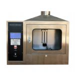
Fire-resistant of Circuit integrity Testing Equipment

Fire-resistant of Circuit integrity Testing Equipment

Application
It is applicable to fire-resistant cables with a rated voltage not exceeding 600/1000V and an outer diameter of no more than 20mm on fire strips
Whether the integrity of the circuit is maintained under the component.
This testing machine includes fire resistance tests, water spray fire resistance tests and mechanical fire resistance tests.
Standard
(GB/T19216.11-2003) IEC 60331-11:1999, Tests for electric cables under fire conditions -- Circuit integrity -- Part 11: Apparatus -- Fire alone at a flame temperature of at least 750˚C
(GB/T19216.21-2003) IEC 60331-21:1999, Tests for electric cables under fire conditions -- Circuit integrity -- Part 21: Procedures and requirements -- Cables of rated voltage up to and including 0.6/1kV
(GB/T19216.23-2003) IEC60331-23:1999, Tests for electric cables under fire conditions -- Circuit integrity -- Part 23: Procedures and requirements -- Electric data cables
(GB/T19216.25-2003) IEC60331-25:1999, Tests for electric cables under fire conditions -- Circuit integrity -- Part 25: Procedures and requirements - Optical fibre cables
(GB/T19216.1-2003) IEC 60331-1:2018, Tests for electric cables under fire conditions -- Circuit integrity -- Part 1: Test method for fire with shock at a temperature of at least 830℃ for cables of rated voltage up to and including 0,6/1,0 kV and with an overall diameter not exceeding 20mm.
(GB/T19216.12-2003) IEC 60331-12:2002, Tests for electric cables under fire conditions -- Circuit integrity -- Part 12: Fire with shock at a flame temperature of at least 830℃.
(GB/T19216.31-2003) IEC 60331-31:1999,: Tests for electric cables under fire conditions -- Circuit integrity -- Part 31 Fire with shock Cables of rated voltage up to and including 0.6/1kV
BS 6387:2013, Test method for resistance ti fire of cables required to maintain to maintain circuit integrity under fire conditions
BS8491:2018, Method for assessment of fire integrity of large diameter power cables for use as components for smoke and heat control systems and certain other active fire safety systems.
Main parameters:
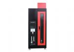
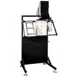
l Fire resistance test device: (IEC60331, BS6387 shared) two blowtorch

Fire resistance test device
1) Sample support device: The sample bracket has a total of 3 support wire rings, the inner diameter of the metal ring is about 150 mm, and is manufactured with a diameter of (10±2) mm round steel rod. During the test, the sample is placed on the support ring. One end of the sample is fixed and clamped to prevent movement, and the other end is supported to allow longitudinal movement of the sample due to thermal expansion.
2) Continuity checking device: during the test, the current used for continuity checking is passed through all conductors of the cable. The current is provided by a three-phase star-connected transformer with sufficient capacity to maintain the required test voltage when the maximum allowable leakage current is reached. At the OTHER end of the sample, each conductor or group of conductors is connected to an appropriate load and an indicator device (such as a light bulb) to form a current (a current stabilizer can be added if necessary). The current through each conductor or group of conductors is 0.25A at the test face voltage.
3) Fuse: 2A fuse, in accordance with IEC 60269-3:2010 fuse A-D, model DII.
4) Test voltage (phase voltage) : 0--1000V continuously adjustable.
5) Heat source: a propane gas blowtorch with a venturi mixer with a nominal length of 610mm. The nominal width of the fire-breathing surface is 15mm. There are three staggered rows of drilling holes with a nominal diameter of 1.32mm and a center distance of 3.2mm on the fire-breathing surface.
6) Temperature measurement: Type K thermocouple with Φ1.5mm mineral insulated stainless steel sheath (according to BS EN 60584-1 standard). Position the blowtorch approximately 45mm(x mm) horizontally from the thermocouple and 75mm(y mm) vertically down from the center line of the thermocouple. The burner was lit and gas and air supply adjusted until the flame temperature was stable at 950°C±40°C for at least 5 min recording. At this time, the value of gas and air flow is recorded, and the burner is turned off.
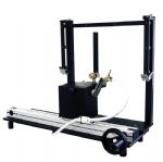
l Impact device (IEC 60331, BS6387 shared)

Impact test device (right part)
1) The test ladder is composed of steel frames. In order to adapt to the test of cables of different sizes, the two vertical members located in the center of the test steel ladder on the test frame can be adjusted, with a length of about 1200mm and a height of about 600mm, as shown in FIG. 1 below. If the weight is needed, it should be placed on the steel support.

Figue 1
2) The impact device consists of a low carbon steel round rod with a diameter of 25±0.1mm and a length of 600±5mm. The axis divides the round rod into two unequal lengths, namely 400±5mm and approximately 200mm, respectively, as shown in Figure 1 and Figure 2

Figure 2
3) Heat source: The heat source shall be a propane gas blowtorch with a nominal nozzle length of 500mm with a Venturi mixer. Central air supply blowtorch is recommended. The nominal width of the nozzle should be 15mm. The nozzle shall have three staggered rows of holes with a nominal diameter of 1.32mm and a center distance of 3.2mm. In addition, a row of small holes on each side of the nozzle is allowed to serve as guide holes to maintain the flame burning.
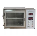
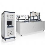
Water and fire resistance test: (BS6387)

Water and fire resistance test bench (sprinkler device)

Water and fire resistance test bench (fire-resistant part)
1) Sample support device: The test is connected to the metal support body composed of two steel bars with width of 25mm±1mm, length of 1150mm±25mm and thickness of 5.5mm±1mm through a copper clamp. The spacing of the clamps is 200mm±10mm, the assembly with the cable is supported in the test frame, and the frame is grounded.
2) Continuity checking device:
2.1) During the test, the current used for the continuity check is passed through all conductors of the cable, and the current is provided by a three-phase star-connected transformer with sufficient capacity to maintain the required test voltage up to the maximum allowable leakage current. At the OTHER end of the sample, each conductor or group of conductors is connected to an appropriate load and an indicator device (such as a light bulb) to form a current (a current stabilizer can be added if necessary). The current through each conductor or group of conductors is 0.25A at the test face voltage.
2.2) Fuse: 2A fuse, in accordance with IEC 60269-3:2010 fuse A-D, model DII.
2.3) Test voltage: 0--1000V continuous adjustable (line voltage 1000V, phase voltage 600V).
2.4) Heat source: propane gas blowtorch with a venturi mixer with a nominal surface length of 500mm. The nominal width of the fire-breathing surface is 10mm. There are three staggered rows of drilling holes with a nominal diameter of 1.32mm and a center distance of 3.2mm on the fire-breathing surface.
2.5) Temperature measurement: using Φ1.5mm mineral insulated stainless steel sheath K type thermocouple (in line with BS EN60584-1 standard) measurement; During the test, the thermocouple was placed in a position on the lower surface of the cable sample. The burner was lit and the gas and air supply adjusted until the flame temperature was stable at 650°C±40°C for at least 5 min recording. At this time, the value of gas and air flow is recorded, and the burner is turned off.
2.6) Water spray: the spray head is fixed on the test frame and in the middle position of the burner assembly, and the water spray rate is between 0.25L/m2/s and 0.30L/m2/s. The rate was measured using a collection tray 400±5mm long and 100±5 mm wide, which should be placed in the center of the sample with the long axis along the cable axis.
Impact and spray test device: (BS8491)

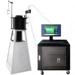
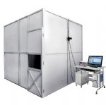
27m³ Test Chamber

1) In order to avoid inconvenient adjustment and installation, the plate is assembled on site.
2) Internal dimension: L3000*W3000*H3000(mm)
3) Structure: Front with glass observation window
4) The top is equipped with an exhaust fan.
- Toys Testing Equipment
- Footwear Testing Equipment
- Tensile Testing Machine
- Environmental Test Chamber
- Building Material Flammability Test Equipment
- Paper Testing Equipment
- Spectacle Frames Testing Equipment
- Oil Analysis Testing Equipment
- Lab Test Equipment
- Electronic Testing Equipment
- Stationery Testing Equipment
- Flammability Test Equipment
- Furniture Testing Machine
- Textile Testing Equipment