English
 中文
中文 Español
 française
 العربية
 Русский
 Toys Testing Equipment
 Physical & Mechanical Testing
- Flammability Testing
- Clamps for Toys Testing
- Electronic Toy Testing Equipment
- ISO8124-4,EN71-8
- Footwear Testing Equipment
- Fatigue Testing Equipment
- Flexing Test Equipment
- Impact Testing Equipment
- Abrasion Testing Equipment
- Waterproofness Tester
- Friction & Slip Testing
- Tensile Testing Machine
- Environmental Test Chamber
- Building Material Flammability Test Equipment
- Paper Testing Equipment
- Spectacle Frames Testing Equipment
- Oil Analysis Testing Equipment
- Lab Test Equipment
- Electronic Testing Equipment
- Stationery Testing Equipment
- Flammability Test Equipment
- Furniture Testing Machine
- Mattress Testing Machine
- Table Testing Machine
- Chair Testing Machine
- Textile Testing Equipment
- Fabric and Garment Testing Instruments
- Color Fastness Testing Equipment
- Toys Testing Equipment
- Footwear Testing Equipment
- Tensile Testing Machine
- Environmental Test Chamber
- Building Material Flammability Test Equipment
- Paper Testing Equipment
- Spectacle Frames Testing Equipment
- Oil Analysis Testing Equipment
- Lab Test Equipment
- Electronic Testing Equipment
- Stationery Testing Equipment
- Flammability Test Equipment
- Furniture Testing Machine
- Textile Testing Equipment
- Toys Testing Equipment
- Physical & Mechanical Testing
- Flammability Testing
- Clamps for Toys Testing
- Electronic Toy Testing Equipment
- ISO8124-4,EN71-8
- Footwear Testing Equipment
- Fatigue Testing Equipment
- Flexing Test Equipment
- Impact Testing Equipment
- Abrasion Testing Equipment
- Waterproofness Tester
- Friction & Slip Testing
- Tensile Testing Machine
- Environmental Test Chamber
- Building Material Flammability Test Equipment
- Paper Testing Equipment
- Spectacle Frames Testing Equipment
- Oil Analysis Testing Equipment
- Lab Test Equipment
- Electronic Testing Equipment
- Stationery Testing Equipment
- Flammability Test Equipment
- Furniture Testing Machine
- Mattress Testing Machine
- Table Testing Machine
- Chair Testing Machine
- Textile Testing Equipment
- Fabric and Garment Testing Instruments
- Color Fastness Testing Equipment
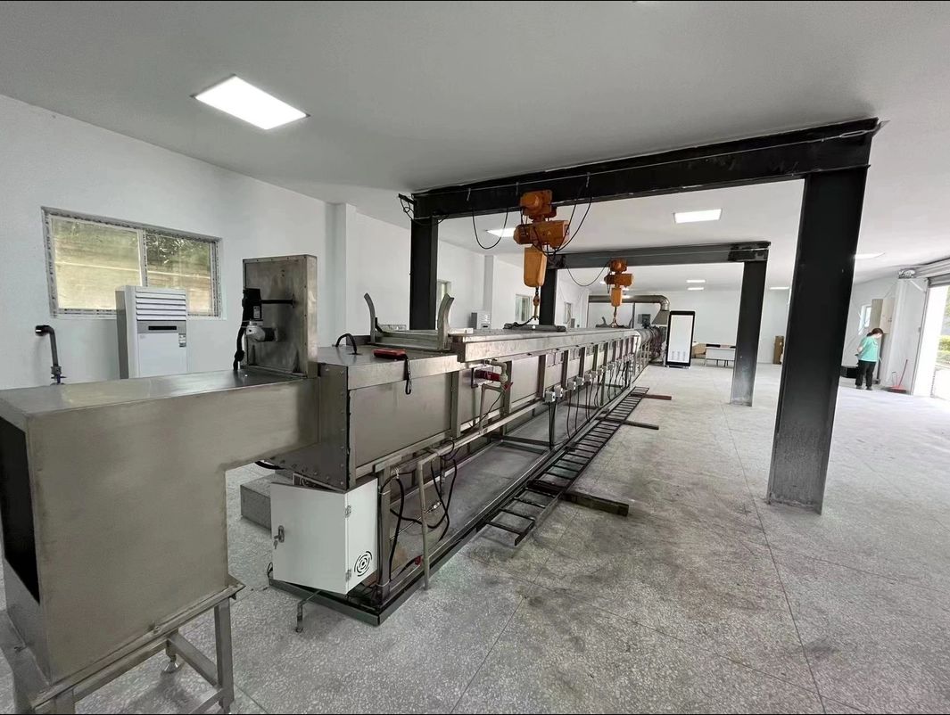
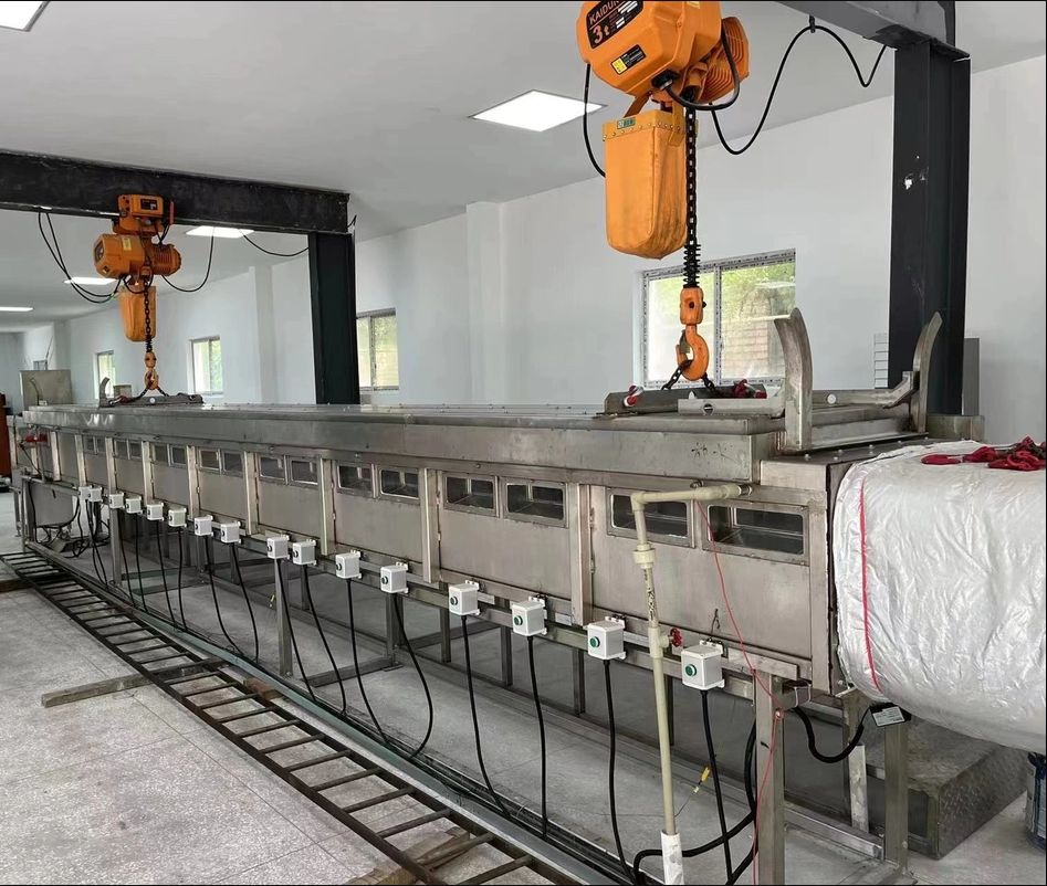
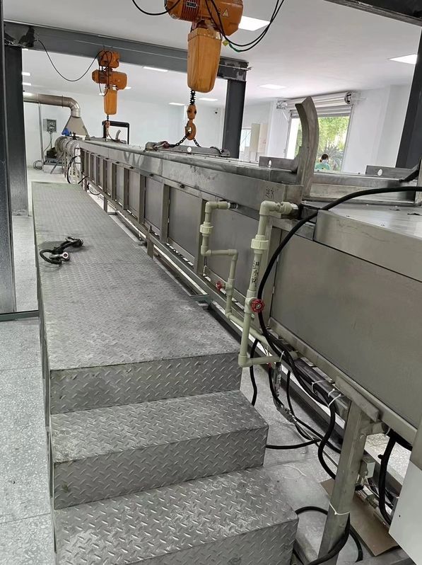
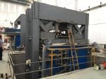
ASTM E84 Steiner Tunnel Furnace chamber

ASTM E84 Steiner Tunnel Furnace chamber


Design referenced to the below standards
ASTM E84: Standard Test Method for Surface Burning Characteristics of Building Materials.
Steiner Tunnel Furnace Chamber Design Proposal
2.1 Summary
This technical solution is based on the integration of instrumentation and electricity, and uses OMRON's advanced multi-function control system to combine ignition sequence, combustion safety, electrical interlocking, automatic temperature control, manual adjustment, monitoring alarm, and data acquisition / communication into one. The furnace temperature and pressure control system uses the control system composed of OMRON controller + Advantech + Visual Basic software for automatic control and online monitoring. The upper computer Advantech operation station operates and monitors the necessary process parameters of the furnace. It has data storage, inspection and printing. , And other functions. At the same time, according to the requirements of UL910 / NFPA262 standards, a dedicated combustion test room can be set up for combustion test, This combustion test room effectively isolates the Steiner horizontal tunnel furnace,Install the smoke density measuring end in a dark room,Avoid interference from external light;Burn test area, adopt independent design method,according to the standard requirement, should provide free airflow. Therefore, during the entire test, keep the room under controlled air pressure of 0-12 Pa (0-0.05 inch water volume) higher than the surrounding air pressure.,The temperature is maintained at 18.3 ° C-26.7 ° C (65 ° F-80 ° F) and a relative humidity of 45-60%.
2.1.1 Design conditions
n Furnace type: Steiner horizontal tunnel furnace
n Furnace main dimensions: Furnace size 7620mm * 451mm * 305mm
n Number of furnace covers: Steiner horizontal tunnel furnace: 1 furnace cover
n Furnace working temperature: up to 600 ℃ (flue gas temperature)
n Fuel: Methane with a purity of at least 95%
n Fuel calorific value: 3500btu / lb
n Fuel pressure: 0.4-0.5MPa
n Burner model: 3/4 inch U-shaped double burner
n Exhaust temperature of flue pipe: <250 ° C, usually the flue gas temperature is controlled within 200 ° C.
n Test method of the tested object: Horizontal component furnace-furnace ceiling hoisting
Design conditions 15KVA, 380V/220V, 3 phases. Notes: Voltage can be customized.
2.1.2 Structural parameters
2.1.3 n Furnace structure: refractory brick + SUS304 stainless steel plate
2.1.4 n Furnace bottom structure: refractory brick 229mm x 114.5mm x 64mm
2.1.5 n Type and quantity of burner: 1 3 / 4-inch U-shaped double burner.
2.1.6 n Smoke exhaust method: mechanical smoke exhaust + cold air mixing on the back wall
2.1.7 Furnace door opening method: Horizontal component furnace-hoist ceiling hoisting and translation (customer built)
2.1.8 Furnace diagram

2.1.4 Purpose:
Used for ASTM E84 test of building materials.
2.1.5 Design principles
Adopt the principles of advanced technology, reliability, safety, and economic rationality
2.2 Furnace structure
2.2.1 Furnace Shell
The furnace steel structure is composed of square tube / rectangular tube end, side upright and furnace body steel plate. After being welded with high strength, it forms a solid whole, which can be used without deformation for a long time.
Furnace body steel plate:SUS304,δ=3mm
Furnace frame:Q235-A ,Square tube / rectangular tube
Furnace transverse bars:Q235-A ,Square tube/ rectangular tube
Window:Quartz glass and tempered glass double layer combination,δ=3mm,70mm±6mm×280mm±38mm
The shutter provides a 74~78mmopening high from the floor level of the chamber. The shutter can be adjusted.
The burner is located in 1372±10mm from the air inlet. air velocity port is 381±5mm from the air inlet.
locations of thermocouples
1. A 18 awg thermocouple is located in the 7000±10mm from burner port( exposed on the air);
2. A 18 awg thermocouple is located in the 3960±10mm from burner port(embedded below the floor);
A 18 awg thermocouple is located in the 7090±10mm from burner port (embedded below the floor).
The ledges are manufactured from Q235-A steel, with water cooled device.

2.2.2 Furnace Resistance materials
The test furnace masonry is consisted of refractory bricks, At the same time, in order to provide the air turbulence required during the combustion process,Obtained by placing six 229mm long x 114.5mm wide x 64mm thick heat-resistant refractory bricks(Long vertical line of the wall and 114.5mm long parallel line). According to the measured burner centerline to the refractory brick centerline,Refractory bricks near the window (without obstructing the windows) 1.98m±152mm、3.96m±152mm and 5.79±152mm,the distance of another side is 1.37m±152mm、2.90m±152mm and 4.88m±152mm.
The highest Temperature resistance: 1427℃ (2600℉)
Bulk Density: 0.77±0.046g/cm3
Thermal conductivity at average temperature:
260℃(500℉) 0.23W/m·℃
538℃(1000℉) 0.27 W/m·℃
815℃(1500℉) 0.32 W/m·℃
1093℃(1500℉) 0.37 W/m·℃
2.2.3 Furnace door and Pressing mechanism
Operation Furnace door above the furnace body, as a sealing device for the furnace body. Composed of metal and inorganic insulators, Insulators composed of inorganic insulators, 51mm ± 6mm thick inorganic insulator material
Horizontal furnace door is welded by section steel, use self-weight vertical lifting method to compact, to observe the condition of the furnace, observation windows installed on both sides of the furnace wall, to get an effective seal, an effective water seal acts as a seal between the furnace door and the furnace body, Using tap water as the circulating water source can not only provide a seal for the quality inspection of the furnace body and the furnace door, but also take away the heat during the combustion test and effectively protect the furnace body.
The lab should provide the crane to lift the lid.
Max. Effective use temperature up to 1050℃;
Density: 335±5kg/m3;
Thermal Conductivity: 0.085W/mK@400 ℃
Dimension 7620±50mm*451±5mm*305±5mm

2.2.4 Inlet chamber and inlet baffle
The furnace steel structure is composed of square tube / rectangular tube end, side upright and furnace body steel plate. After being welded with high strength, it forms a solid whole, which can be used without deformation for a long time. The air intake baffle is pneumatically controlled and can be opened and closed automatically. Intake chamber This element shall have a rectangular opening of 298.5mm ± 6mm × 464mm ± 6mm to allow air to pass through the nearest baffle into the combustion test chamber.
Furnace steel plate: SUS304, δ = 3mm
Furnace frame: Q235-A, square tube / rectangular tube
Furnace transverse ribs: Q235-A, square tube / rectangular tube
Location of manometer in the diagram.
381±5mm downstream from the inlet shutter


2.2.4 Smoke exhaust system and furnace pressure control system
The exhaust of the furnace body adopts the form of mechanical exhaust to ensure that the pressure and temperature in the furnace and the exhaust gas meet the standard requirements. It includes transition section, smoke exhaust pipeline, automatic butterfly valve, and differential pressure control system. Transition section: a rectangular section stainless steel element with a length of 902mm ± 6mm × 686mm ± 6mm in width × 438mm ± 6mm in height,and a 457mm±6mm It consists of a long rectangular elliptical transitional section, and the rectangular elliptical transitional section is connected to an exhaust pipe with an inner diameter (I.D.) of 406mm ± 3m. The exterior of the transitional section is insulated with a 51mm ceramic fiber cover, with a density of 130kg / m3. The steel plate is SUS304, δ = 1.5mm. Exhaust pipe: 406mm ± 3mm I.D. exhaust pipe, extending from the exhaust end of the transition section from 4.88m to 5.49m to the center line of the smoke measurement system, so as to provide a completely mixed exhaust gas flow. The exhaust pipe opening shall be insulated with a high temperature inorganic material of at least 51mm, from the beginning of the exhaust transmission part to the smoke detection system. The steel plate is SUS304, δ = 1.5mm. Differential pressure control system: The detector should consist of a stainless steel column with a column length rated twice the outer diameter of the column, the length of the draft gauge tap is 25±12mm. 25±12mm, and a central solid partition. The bidirectional probe is connected to a pressure sensor, which can effectively read the pressure value in the furnace


Exhaust damper:406mm I.D. The single-piece pipe flow control damper of the pipe is installed at 1.68m ± 0.15m below the exhaust pipe of the smoke measurement system, and the center line is to the center line.
The relative positions of exhaust transition components exhaust ducts, smoke measurement systems, and exhaust duct dampers are shown in the figure.
In order to maintain control of the air flow during the entire test process, the exhaust pipe damper should be controlled by a closed-loop feedback system that forms effective communication with the differential pressure control system.

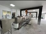
2.2.5 Effect drawing:Steiner Tunnel Furnace Chamber

2.3 Burning system
2.3.1 Burner
The gas to the burner should be provided by a single inlet duct, Disperse through the T-section to each burner. Elbow tube rated for 19mm (0.75 inch) air outlet, the burner plane should be parallel to the test room floor. This allows the gas to be directed directly up the sample. Each burner uses the 102mm ± 6mm centerline at each side of the centerline of its combustion test chamber to make up positions so that the burner flame is evenly distributed.
Use electronic ignition system to ignite gas stove from a long distance, guaranteed safety performance, High voltage igniter, 44KV, 50mA, minimum voltage of ignition electrode is 1.8kVp.
2.3.2 Valve group
2.3.3.1 Gas pipeline system
Methane with a purity of not less than 95% is sent to the furnace through ball valves, pressure reducing valves, pressure gauges, two solenoid valves, and mass flow controllers.
2.3.3.2 Gas pipeline components:
① Pressure reducing valve:Japan Ito Mirai pressure reducing valve with inlet pressure compensation and zero pressure shutdown,According to the set spring tension. The outlet pressure of the pressure regulating valve remains constant and is not affected by changes in gas flow. When no gas flows through the pressure reducing valve, the regulating valve closes automatically.
② Solenoid valve: open to cut off, quick closing time 1 second, play a fast response and fast cut off. Maximum working frequency: 20 times / minute, maximum working pressure: 360mbar.
③ Pressure switch pressure gauge: measure the pressure of the main gas pipeline, and pave the way for the adjustment of the gas pressure during the commissioning phase, which can ensure that the pressure of the gas pipeline is maintained at a normal level. Pressure range: 0 ~ 20kpa.
④ Mass flow controller: American AALBORG mass flow controller, 316 stainless steel, maximum pressure 1000psig (70bar), leakage rate less than 1 × 10⁻⁷ sml / s, calibrated by NIST, 0 ~ 5VDC and 4 ~ 20mA signal, circuit protection, Control speed ≤ 2s, control accuracy is ± 1% FS, repeatability ± 0.5FS, temperature range 0 ~ 50 ℃, humidity range 0 ~ 90%, digital display, gas supply meets 5000Btu (5.3MJ) / during automatic control test Min heat requirement, the software automatically records the amount of gas used; it can cooperate with the burner output standard 5.3MJ / min heat, and according to different standards, the gas flow can be controlled by the mass flow meter, the measurement range is 0 ~ 160L / min, which can change the burner Calorific value output, the maximum output energy can reach 100MJ / min;
⑤Gas filter: Italy Guilong gas filter, filter cotton aperture <50um
2.4 Smoke Density Measure System
2.4.1 Smoke Density measure system light source
An American GE 12V sealed lamp, clean lens, automatic spotlight mounted on the cross section of the exhaust duct, the light beam should shine upward along the vertical axis of the exhaust pipe, The cylindrical beam should pass through the openings of 76mm ± 3mm in diameter at the top and bottom of the 406mm (16 inch) I.D. pipe, and the combined beams should be concentrated at the center of the photovoltaic cell.
2.4.2 Receiving device for smoke density measurement system
Photocells that output directly according to the proportion of light received should be placed above the light source, and the total distance from the path of the light to the battery is 914mm ±102mm. Photocells should be connected to recording equipment, which is used to show that the incident light in the disappearing smoke is attenuated due to special circumstances and other effects.

2.4.4 Heating curve:Meet the requirements of rising and falling temperature control and furnace temperature deviation.

Red Oak Calibration Curve


Installation Requirement
l Indoor floor mounted, the floor should be solid(concrete floor is recommended) and flat.
l The space should be at least 12m(L)*6m(W)*4m(L).
l The space should provide the crane for the lid lifting, the capacity should be at least 5tons.
l Power supply: 380V, 50/60Hz, 3 phases, capacity not less than 15KVA.
l City water supply.
l Natured gas or bottled methane supply.
- Toys Testing Equipment
- Footwear Testing Equipment
- Tensile Testing Machine
- Environmental Test Chamber
- Building Material Flammability Test Equipment
- Paper Testing Equipment
- Spectacle Frames Testing Equipment
- Oil Analysis Testing Equipment
- Lab Test Equipment
- Electronic Testing Equipment
- Stationery Testing Equipment
- Flammability Test Equipment
- Furniture Testing Machine
- Textile Testing Equipment